We'd like to send you notifications of the latest posts and updates.
We'd like to send you notifications of the latest posts and updates.
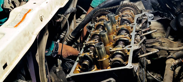
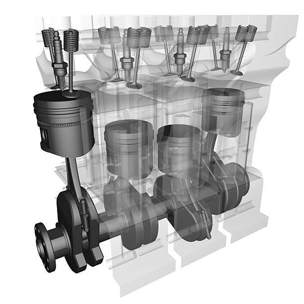
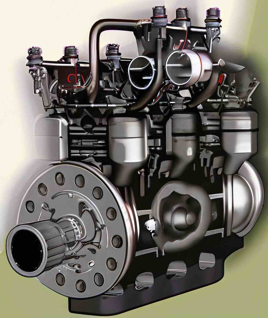
Engine parts requiring lubrication:
Types of lubrication systems for I.C. engines:
1. Wet sump lubrication system.
2. Dry sump lubrication system.
3. Mist lubrication system.
Utilizes a large oil sump at the crank chamber base, drawing oil with a low-pressure pump to various parts before returning it to the sump.
(i) Found in small four-stroke stationary engines, where caps on big end bearings have scoops that dip into oil troughs, directing oil through holes to lubricate parts. Suitable for low to medium-speed engines but inadequate for high-performance ones.
(i) Combines splash and pressure systems, drawing oil from the sump through a filter and delivering it at 1 bar pressure to main bearings. Offers cost-effective lubrication for higher loads and speeds.
Pumps oil under pressure from the sump to various points, ensuring high bearing pressure and rubbing speeds.
Oil from the sump is routed to a separate tank outside the engine, then pumped to the cylinder through filters and an oil cooler. Common in high-capacity engines.
Used in two-stroke cycle engines by adding 2 to 3 percent oil to the fuel tank, inducing a mist through the carburetor into the cylinder. Achieving the right F/A ratio is crucial, with advantages including simplicity and low cost, but disadvantages such as exhaust emissions and oil burning.
1. Simple system.
2. Low cost, as no oil pump or filter is required.
The cylinder, small end bearing (gudgeon pin),valve gear pins, rocker shaft, crankpins etc. are lubricated by drip system.
In drip system oil is fed to machine parts drop by drop, from an oil cup. Although it is not an efficient method yet it is often the most convenient way of lubricating the external parts of engines and machines. Valve gear pins, rocker shafts, main bearings of small engines, crankpins, cross head pins, line shaft bearings, and many other machine and engine parts are lubricated in this fashion.
The connecting rod is dipped into the oil of the crankcase. At the time of rotation the oil is splashed due to centrifugal force and it reaches the different parts requiring it. This type of lubrication is suitable for a crankshaft speed of 200 r.p.m. or more. The oil must be filtered or renewed periodically. Also the level of the oil should be maintained.
The ball and roller bearings are lubricated for the following purposes :
For lubricating the ball and roller bearings, generally oil or light grease is used. Only pure mineral oil or a calcium-base grease should be used. If there is a possibility of moisture contact, then potassium or sodium base greases may be used. Another additional advantage of the grease is that it forms a seal to keep out dirt or any other foreign substance. The temperature should be kept below 90°C and in no case a bearing should operate above 150°C.
All the lubricating oil (utilized for lubrication purpose) from the oil sump, must pass through an oil filter before it is delivered to the engine bearings. Bearings maintain very close tolerances and are susceptible to be harmed by any foreign abrasive material entering the lubrication line.
The filter arrangement may be of the following two types: (i) By-pass type; (ii) Full-flow type.
(1) In this arrangement only a small portion of the lubricating oil is passed through the filter and the remaining lubricating oil is directly supplied to the bearings by the oil pump at pre-set pressure, determined by the pressure regulating valve. Consequently, a portion of the oil is continuously filtered.
(2) Since quantities of oil flowing through the filter are small, a very fine filter or a special filter impregnated with resin to prevent disintegration due to moisture is used. Such a fine paper/filter will eliminate all harmful contaminants.
(A) In this filter arrangement, the entirety of the oil is filtered before it is supplied to various bearings. Thus, the size of the filter is comparatively large.
(B) In this case, it is scarcely possible to eliminate very fine particles because of the high pressure required to pump oil through such filters.
C. All the lubricating oil, in the normal course, should be filtered approximately every half minute. A pressure relief valve is used to prevent excessive pressure build-up after a cold start.
Crankcase ventilation is necessary due to the following two reasons:
(i) Various contaminants such as water, gasoline, blowby gases, etc., enter the crankcase due to several reasons, and may cause sludge and corrode metal parts.
(ii) To alleviate any pressure build-up in the crankcase which may cause leakage of the crankshaft seal.
In practice, the following two types of ventilation systems are used:
(i) In this system, fresh air supply is introduced into the crankcase during the compression stroke (due to the creation of a small vacuum). The entering air picks up the contaminants (water vapor, gases, and H2SO4 vapor) and discharges them into the atmosphere during the expansion stroke. (ii) The primary disadvantage of this system is that the natural ventilation is quite inadequate during idling or running at low speeds.
-In a closed system, the fresh air supply is drawn into the crankcase from the carburetor.
-The air cleaner and the breather outlets are connected to the intake manifold through a PCV valve to ensure the combustion of all the crankcase gases in the combustion chamber.
Safety Manufacuturing PPE Automation & Mechanization Friction Lubricants Classification of manufacturing advantage and dis. LPG 5S News fire prevention ci vs si engine Gear LPG vs petrol
Safety Manufacuturing PPE Automation & Mechanization Friction Lubricants Classification of manufacturing advantage and dis. LPG 5S News fire prevention ci vs si engine Gear LPG vs petrol
To get first Notification: