COMPONENTS OF I.C. ENGINES
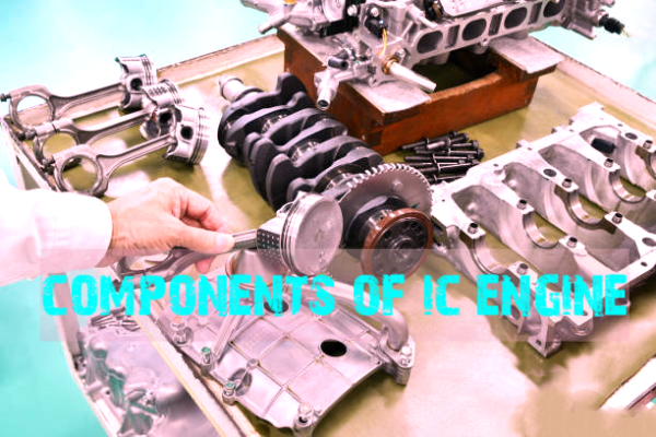
Here follows the detail of the various parts of an internal combustion engine.
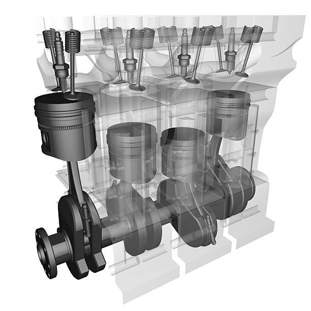
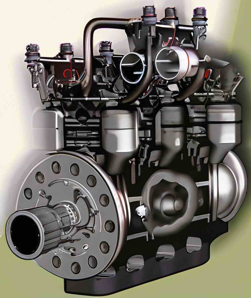
A cross-section of an air-cooled I.C. engine with principal parts
A. Parts common to both petrol and diesel engine :
- Cylinder
- Cylinder head
- Piston.
- Piston rings
- Gudgeon pin.
- Connecting rod
- Crankshaft
- Crank.
- Engine bearing.
- Crankcase.
- Flywheel
- Governor.
- 13. Valves and valve operating mechanisms.
B. Parts for petrol engines only :
- Spark plugs.
- Carburettor.
- Fuel pump.
C.Parts for Diesel engine only :
- Fuel pump.
- Injector.
A. Parts common to both petrol and diesel engines :
1. Cylinder:
The cylinder contains compressed gas and guides the piston. It is in direct contact with the products of combustion and must be cooled. The optimal shape comprises a simple cylindrical barrel in which the piston glides. The piston's movement or stroke is typically longer than the bore, known as the "stroke bore ratio." The upper part includes a combustion or clearance space where ignition and combustion occur. In reality, it is essential to deviate from the ideal hemispherical slope to accommodate valves, spark plugs, etc., and regulate combustion. Sections of an air-cooled cylinder and a liquid-cooled cylinder. The cylinder is constructed from tough grade cast iron and is usually cast in one unit.
2.Cylinder head:
The main purpose of the cylinder head is to seal the working ends of the cylinders and not to permit entry and exit of gases on cover head valve engines. The inside cavity of head is called the combustion chamber, into which the mixture is compressed for firing. Its shape controls the direction and rate of combustion. Heads are drilled and tapped with correct thread to take the ignition spark plug. All the combustion chambers in an engine must be of same shape and size.
The shape may be in part controlled by the piston shape.
The cylinder head is usually made of cast iron or aluminium.
3. Piston:
A piston is fitted to each cylinder as a face to receive gas pressure and transmit the thrust to the connecting rod. The piston must :
(i) give gas tight seal to the cylinder through bore,
(ii) slide freely,
(iii) belight and
(iv) be strong.
The thrust on the piston on the power stroke tries to tilt the piston as the connecting rod swings, side ways. The piston wall, called the skirt must be strong enough to stand upto this side thrust. Pistons are made of cast iron or aluminium alloy for lightness. Light alloy pistons expand more than cast iron one therefore they need large clearances to the bore, when cold,or special provision for expansion. Pistons may be solid skirt or split skirt.
4. Piston rings:
To provide a good sealing fit between the piston and cylinder, pistons are equipped with piston rings.. The rings are usually made of cast iron of fine grain and high elasticity which is not affected by the working heat. Some rings are of alloy spring steel. They are split at one point so that they can be expanded and slipped over the end of the piston and into ring
grooves which have been cut in the piston. When the piston is installed in the cylinder the rings are compressed into ring grooves which have been cut in the piston.
Small two stroke cycle engines have two rings on the piston. Both are compression rings. Two rings are used to divide up the job of holding the compression and combustion pressure. This produces better sealing with less ring pressure against the cylinder wall.
Four stroke cycle engines have an extra ring, called the oil control ring . Four stroke cycle engines are so constructed that they get much more oil in the cylinder wall than do two stroke cycle engines. This additional oil must be scraped off to prevent it from getting up into the combustion chamber, where it would burn and cause trouble.
compression rings have a rectilinear cross-section and oil rings are provided with a groove in the middle and with through holes spaced at certain interval from each other. The oil collected from the cylinder walls flows through these holes into the piston groove whence through the holes in the body of the piston and down its inner walls into the engine crankcase.
5. Gudgeon pin (or wrist pin or piston pin):
These are hardened steel parallel spindles fitted through the piston bosses and the small end bushes or eyes to allow the connecting rods to swivel. Gudgeon pins are a press fit in the piston bosses of light alloy pistons when cold. For removal or fitting, the piston should be dipped in hot
water or hot oil, this expands the bosses and the pins can be removed or fitted freely without damage.It is made hollow for lightness since it is a reciprocating part.
6. Connecting rod:
The connecting rod transmits the piston load to the crank, causing the latter to turn, thus converting the reciprocating motion of the piston into a rotary motion of the
crankshaft. The lower or “big end” of the connecting rod turns on “crank pins”.The connecting rods are made of nickle, chrome and chrome vandium steels. For small engines the material may be aluminium.
7. Crank:
The piston moves up and down in the cylinder. This up and down motion is called reciprocating motion. The piston moves in a straight line. The straight line motion must be changed to rotary, or turning motion, in most machines, before it can do any good. That is rotary motion is required to make wheels turn, a cutting blade spin or a pulley rotate. To change the reciprocating motion to rotary motion a crank and connecting rod are used. The connecting rod connects the piston to the crank.
8. Engine bearing:
The crankshaft is supported by bearing. The connecting rod big end is attached to the crank pin on the crank of the crankshaft by a bearing. A piston pin at the rod small end is used to attach the rod to the piston. The piston pin rides in bearings. Every where there is rotary action in the engine, bearings are used to support the moving parts. The purpose of bearing is to reduce the friction and allow the parts to move easily. Bearings are lubricated with oil to make the relative motion easier. Bearings used in engines are of two types : sliding or rolling >
The sliding type of bearings are sometimes called bushings or sleeve bearings . The rolling-type bearing uses balls or rollers between the stationary support and the rotating shaft.
9. Crankcase:
The main body of the engine to which the cylinders are attached and which contains the crankshaft and crankshaft bearing is called crankcase. This member also holds other parts in alignment and resists the explosion and inertia forces. It also protects the parts from dirt etc. and serves as a part of the lubricating system.
10. Flywheel:
- A flywheel (steel or cast iron disc) secured on the crank shaft performs the following functions :
- Brings the mechanism out of dead centres.
- Stores energy required to rotate the shaft during preparatory strokes.
- Makes crankshaft rotation more uniform.
- Facilitates the starting of the engine and overcoming of short time over loads as,
for example, when the machine is started from rest.=The weight of the flywheel depends upon the nature of variation of the pressure. The flywheel for a double-acting steam engine is lighter than that of a single-acting one. Similarly, the flywheel for a two-stroke cycle engine is lighter than a flywheel used for a four-stroke cycle engine.Lighter flywheels are used for multi-cylinder engines.
11. Governor:
governor may be defined as a device for regulating automatically output of a machine by regulating the supply of working fluid. When the speed decreases due to increase in load the supply valve is opened by mechanism operated by the governor and the engine therefore speeds up again to its original speed. If the speed increases due to a decrease of load the governor mechanism closes the supply valve sufficiently to slow the engine to its original speed. Thus the function of a governor is to control the fluctuations of engine speed due to changes of load.
12.Valves and valve gears:
With few exceptions the inlet and exhaust of internal combustion engines are controlled by poppet valves. Poppet valves in internal combustion engines are commonly controlled by cam gears or eccentrics. These components are mounted on shafts, driven by gearing at half the speed of the crankshaft, ensuring one rotation per complete engine cycle. The cams or eccentrics lift the valves from their seats against strong springs, opening the ports for inlet and exhaust. The specific design of the cam curves depends on the engine speed and desired valve opening characteristics. This intricate valve gear mechanism ensures precise timing for optimal engine performance.
Valve timing
Theoretically the valves open and close at top dead centre (T.D.C.) or at bottom dead centre (B.D.C.) but practically they do so some time before or after the piston reaches the upper or lower limit of travel.
B. Parts common to petrol engine only :
1.Spark-plug:
The main function of a spark-plug is to conduct the high potential from the ignition system
into the combustion chamber. It provides the proper gap across which spark is produced by applying high voltage, to ignite the combustion chamber.A spark-plug entails the following requirements :
- It must withstand peak pressures up to atleast 55 bar.
- It must provide suitable insulation between two electrodes to prevent short circuiting.
- It must be capable of withstanding high temperatures to the tune of 2000°C to 2500°C over long periods of operation.
- It must offer maximum resistance to erosion burning away of the spark points irrespective of the nature of fuel used.
- It must possess a high heat resistance so that the electrodes do not become sufficiently hot to cause the preignition of the charge within the engine cylinder.
- The insulating material must withstand satisfactorily the chemical reaction effects of the fuel and hot products of combustion.
- Gas tight joints between the insulator and metal parts are essential under all operating conditions.
1.carburettor:
The function of a carburettor is to atomise and metre the liquid fuel and mix it with the air as it enters the induction system of the engine, maintaining under all conditions of operation fuel-air proportions appropriate to those conditions.
All modern carburettors are based upon Bernoulli’s theorem,
C2 = 2gh
3.Fuel pump (for carburettor-petrol engine).
This type of pump is used in petrol engine for supply of fuel to the carburettor. Due to rotation of the crankshaft the cam pushes the lever in the upward direction. One end of the lever is hinged while the other end pulls the diaphragm rod with the diaphragm. So the diaphragm comes in the downward direction against the compression of the spring and thus a vacuum is produced in the pump chamber. This causes the fuel to enter into the pump chamber from the glass bowl through the strainer and the inlet valve, the impurities of the fuel ; if there is any, deposit at the bottom of the glass bowl. On the return stroke the spring pushes the diaphragm
in the upward direction forcing the fuel from the pump chamber into the carburettor through the outlet valve.
C.Parts for Diesel engine only :
Fuel atomiser or injector:
It comprises a nozzle valve (NV) installed in the nozzle body (NB). The nozzle valve is secured on its seat by a spring ‘S’ applying pressure via the spindle E. ‘AS’ serves as the adjusting screw to modify the nozzle valve lift. Typically, the nozzle valve is configured to lift at a pressure ranging from 135 to 170 bar. FP denotes the feeling pin, indicating the proper functioning of the valve. Pressurized oil from the fuel pump enters the injector through passages B and C, lifting the nozzle valve. The fuel flows down the nozzle N and is introduced into the engine cylinder as fine sprays. When the oil pressure drops, the nozzle valve returns to its seat under spring force, cutting off the fuel supply. Any fuel leakage accumulated above the valve is directed to the fuel tank through passage A. Leakage occurs when the nozzle valve is worn out.